| |
| |
Heat recovery system &
plumbing diagrams
for our most popular configurations:
|
|
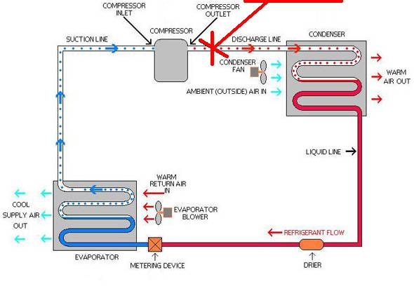
This drawing below shows the logical topology of a standard refrigeration system and shows where the HotSpot heat recovery equipment (Heat Recovery Unit or HRU) is connected. The refrigeration cycle shown below would be applicable to a cooler, freezer, ice maker or air conditioner. If the unit were a heat pump, not shown is a 4-way valve (reversing valve) that would be located between the HotSpot connection and the condenser.
| |
Heat Recovery
Connects Here |
|
|
| |
|
|
Key:
The red dots represent hot high pressure refrigerant gas.
The solid red represents warm high-pressure refrigerant liquid.
Solid blue represents cold low pressure refrigerant liquid.
The blue dots represent warm low pressure refrigerant gas
The HotSpot connects at the hottest point, next to the compressor discharge.
Technical & Sales
Support
1-800-916-2067 or Contact
Us
|
| |
|
| |
|
|
|